A³ Motion Assembly
V03
Drawn, printed, populated, and running — in that order.
The print-ready housing (October 2026)
The v3 housing was rebuilt in FreeCAD from sketches and Part features only, so every part can be changed from its sketch. It prints on a Bambu A1.
assembled |
exploded |
|---|---|
|
|
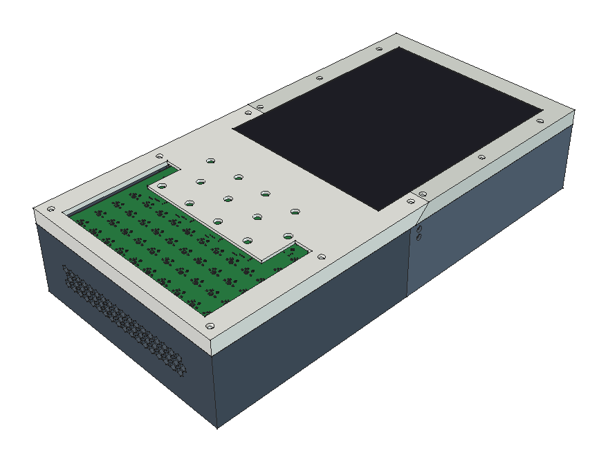
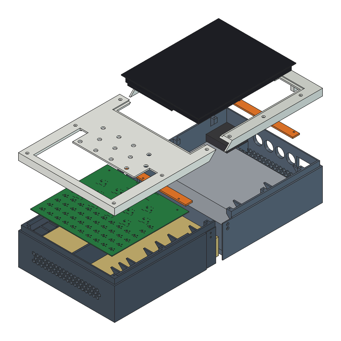
Print: every part is at most 238 × 252 mm. The enclosure and the faceplate are two halves each, joined by 45° scarfs, so no part prints a floating strip. Support only under the 5 mm display ledge of the faceplates.
Fastening: M3 throughout. Twelve countersunk screws hold the faceplate; the enclosure halves join with three screws in the floor and two in each side wall.
Inside: the pad PCB hangs from the faceplate on three standoffs and rests on ledges, a centre rib and wall fins. The display (Winstar WF104GSWFMLHBV#) is held by two clamps over 3 mm foam. The NUC (NUC8i7HNK) slides in from the open end of the top half. A blower (Sunon MF50151VX) draws air from under the display and blows it out through the back wall.
Files: the model is
hardware/housing/freecad/housing_v3.FCStdin a3-motion;hardware/housing/freecad/production/holds every part in print orientation as STL, and one 3MF per plate. More renders are inhardware/housing/images/.Replaced files: this housing overwrote the production files of the earlier v3 under the same names —
housing_v3-motion_box.3mf,housing_v3-motion_pcbCut008.stl,housing_v3-motion_pcbfaceplate.3mfandhousing_v3-motion_pcbfaceplate.stl. A print made from those files before October 2026 is the earlier housing shown below.
The earlier v3 housing, as drawn
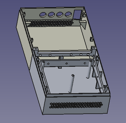
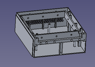
Four views of the enclosure and two of the display bezel. The four round openings in the front wall are the per-channel potentiometers; the perforated band beside them is the vent.
housing |
|||
|---|---|---|---|
|
|
|
|
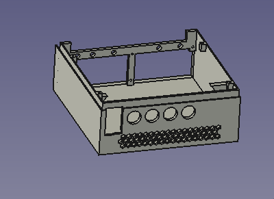
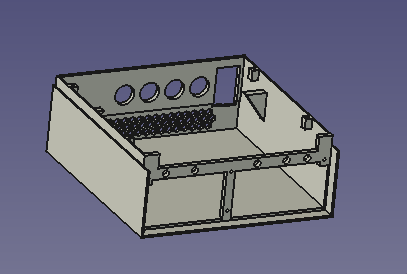
bezel |
assembled |
|
|---|---|---|
|
|
|
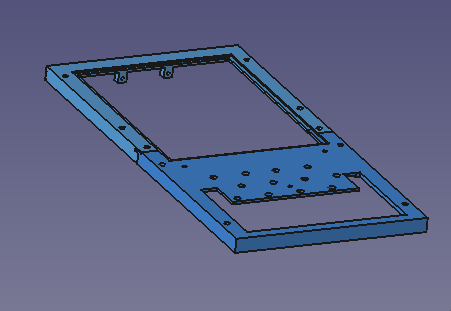
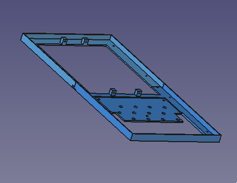
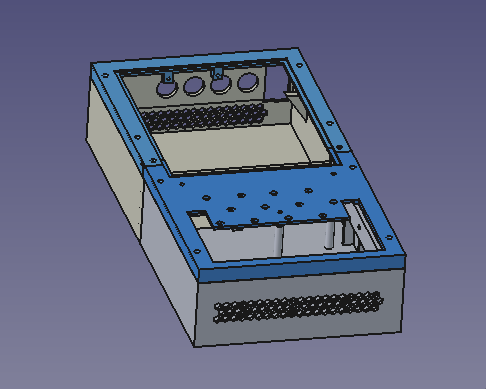
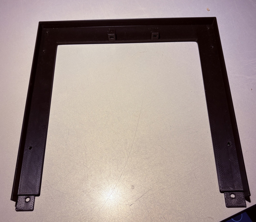
The bezel carries the display’s mounting plate inside its frame, so the screen and the surround are one printed part rather than two to align.
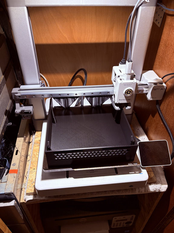
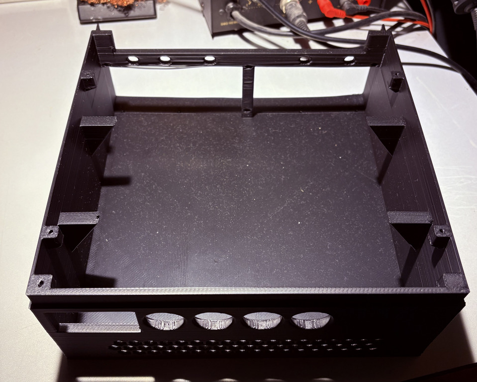
Printed
on the bed |
the housing |
the bezel |
the display mount |
|---|---|---|---|
|
|
|
|
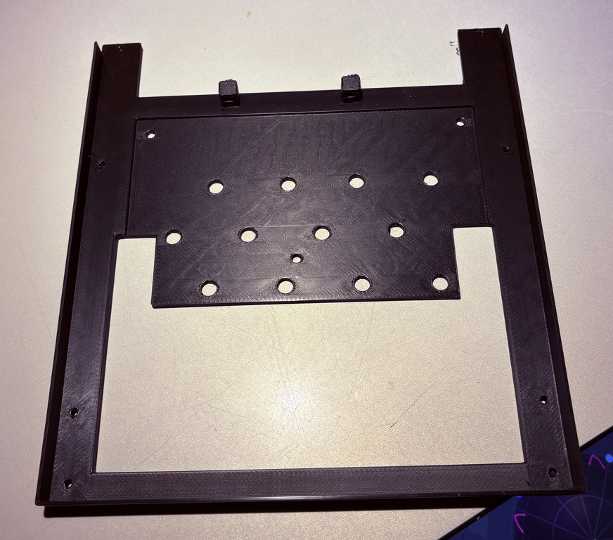
The panel
Four rows of illuminated pads with a column at each end — those two columns are the six function keys, mirrored so either hand reaches them — plus the channel encoders above and the potentiometers along the front.
front |
from inside |
the button matrix, with the ESP32-S3 |
|---|---|---|
|
|
|
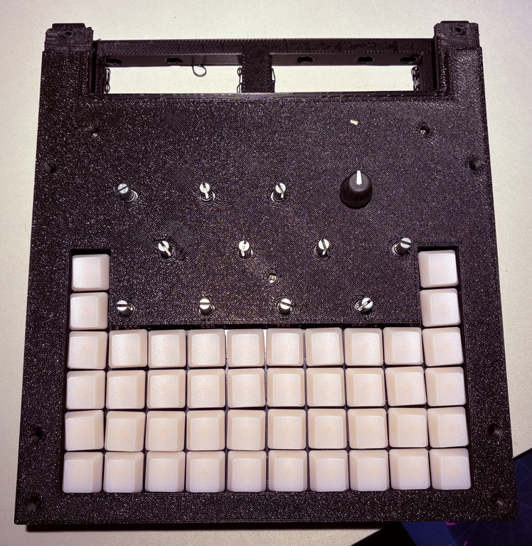
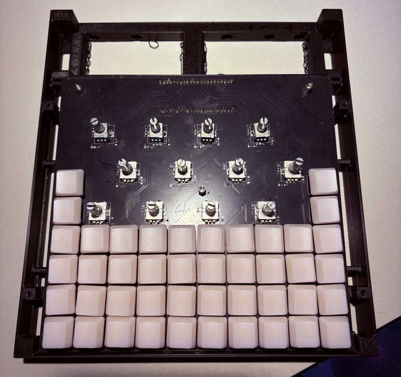
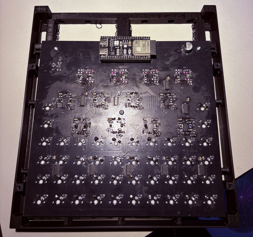
The ESP32-S3 sits at the top of the matrix PCB. What the panel is made of and how it reaches the UI: A³ Motion hardware.
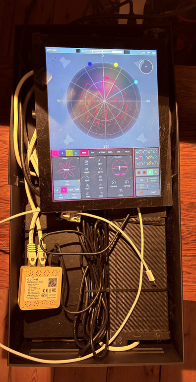
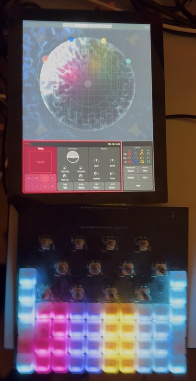
Running
V02

PCB’s
Mainboard PCB V01
front |
back |
|---|---|
|
|


Buttonmatrix PCB V02
front |
back |
action |
|---|---|---|
|
|
|


Housing V02
The housing was build with Blender (.obj) and is ready to print on a 3d-printer (.stl).
draft |
|
|---|---|
|
|


Estimated power consumption, V02
Device |
Watts |
|---|---|
Raspberry Pi 4b |
15W |
Teensy 4.1 |
2.5W |
40 NeoPixel |
11W |
SunFounder Raspberry Pi 4 Display Touchscreen 7 Inch |
3W |
— |
— |
Sum |
31.5W |
V01

V00

